Instructions for setting up the controller
Configuring the controller in the web interface
There are 2 options to enter the controller configuration web interface:
Option #1
In order to determine the network address of the interface of the charging station, you must physically connect to the board through the debugger and find out the address that the station received through it.
Option #2
Send a Get_Communication request via DataTransfer on the server, and the board will send how it is connected and network settings.
Request example:
{
  "GlobalID": "TS-GB_d9ae8c3f8fcf155b",

  "messageId": "Get_Communication"
}
Modem connection response:
{"success":true,"result":{"status":"Accepted","data":
  "Current Communication Parameters:

Modem [
        Module: ...;
        Operator: \"MegaFon\";
        IMEI: 865210032159393;
        IMSI: 250021090923817;
        rssi: 28;
        ber: 0;
      ];
WiFi [NO USE];
"}}
WiFi connection response:
{"success":true,"result":{"status":"Accepted","data":
 "Current Communication Parameters:
Modem [NO USE];
WiFi [
       bssid: d2:39:0f:3d:d9:b4;
       ssid: TOUCH_SERVICE;
       rssi: -34;
       ip: 192.168.188.128;
     ];
"}}
The setting interface displays information about the controller:
- Current software version
- Charge Point SN (Controller Serial Number)
- Flash size (The size of the flash card installed in the controller)

Controller setup.
To configure the controller, you need to select the current version of the controller firmware, for this, in the FW update field, you must enter your address or the path to the json file.
Then press the Set button (allows you to save the set parameter in the device’s memory) or Update now (Update now).

Field Modem APN - displays the access point to connect to the charging station.
Field Wi-Fi User SSID - displays the name of the Wi-Fi network to connect to the charging station.
Field Wi-Fi User PASS - displays the password of the Wi-Fi network to connect to the charging station.
Set button – allows you to save the set parameter in the device memory.

The Working mode (ocpp/offline) field -*** displays the current OCPP or Offline mode version.
To switch to OCPP (commercial mode) or Offline (offline/private mode) use the Set offline mode or Set OCPP mode button.
Field OCPP endpoint UPL – displays the server to which the controller is mapped
The Station OCPPID field is the ID of the controller. ID is generated automatically.
Effective URL field – the field displays the address of the station on the server, it is generated automatically. Consists of OCPP endpoint UPL and Station OCPPID.
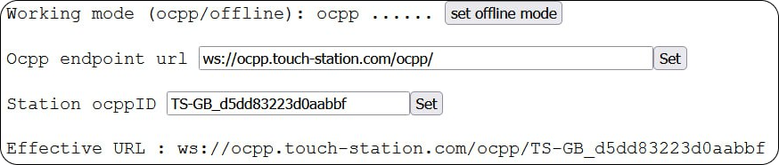
Field OCPP debug – displays service information.

!!!

Actuator type field (fork locking mechanism) – displays the mode of the fork locking mechanism. To switch the mode, use the Set bistable or Set monostable button.
- MONOSTABLE - constant current supply mode, to secure the plug during charging. Upon completion of charging, the voltage is removed from the locking device to remove the cable.
- BISTABLE – mode in which the polarity of the current supply is reversed to switch the state (open/closed). Change happens in impulses.
Connector 1/2 settings – allows you to configure the station ports:
- Field Max amperage (A) - displays the limitation of the charging current. For each port, specify its maximum power.
- Field Energy (Wh) – displays the amount of consumed Watts. Displays data for each individual port.
- Field Meter settings (Imp/kWh) – displays meter data. If one or more counters are installed in the station, indicate their data for each.
Set button – allows you to save the set parameter in the device memory.
EVSE Calibration button – press when setting up a station to calibrate communication channels. If the electric car is connected, do not press. Calibration goes to +12V and -12V levels, if you connect the electric car, everything will be configured incorrectly.
Button Set Factory Settings – reset the controller (station) to factory settings.
Soft Reset button – easy reset of the controller (station), for example, to apply some changes.
Hard Reset button – complete reset of the controller (station), for example, if the station is frozen.
Specifications Controller TOUCH EVSE 1.1
- General view of the board:
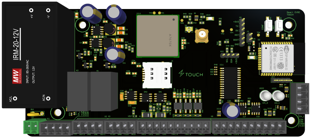
Board dimensions:
- 72x157x40(mm)
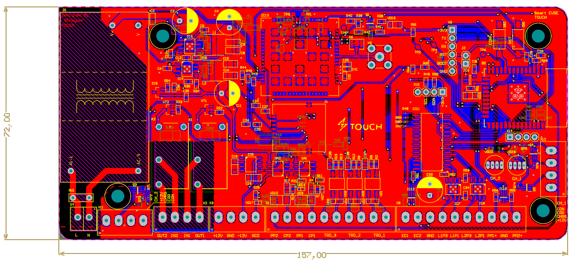
Functionality:
- Wi-Fi and Bluetooth;
- GSM 2G, 3G, LTE, SMA & UFL antenna connector;
- 2 EVSE support (PP/CP/PE);
- 2 LED RGB;
- 2 EXT +12V common anode RGB LED;
- 2 SO Power Meters;
- 2 Plug lock drivers;
- 2 external open drain inputs;
- External hardware WhatchDog;
- Onboard temperature sensor;
- 12C extension port (RFID ready);
- 220AC/+12VDC power supply.
Board pinout
Х4: 220AC power supply (power input ~220V):
- Line (Phase)
- Neutral (Neutral)
X11: EXT +12V common anode RGB LED (External indication 2 ports):
- +12V
- Charging
- Error
- Ready
X2: Controll Relay IN/OUT for EVSE1 & EVSE2 (Intermediate contactor relay):
- OUT2 (Output 2)
- IN2 (Input 2)
- IN 1 (Input 1)
- OUT 1 (Output 1)
X3: DC POWER IN/OUT:
- +12VDC IN/OUT
- GND (Common Ground)
- -12VDC OUT (signal 10ma max)
X1: EVSE 1 + EVSE 2:
- EVSE 2: PP2/CP2
- EVSE 1: PP1/CP1
X8
2 external open drain inputs:
- EC1 (External input, open drain)
- EC2 (External input, open drain)
- GND (Ground)
Plug Lock driver pin 1 & pin 3:
- EVSE1: L1P3, L1P1 (Actuator 1 port (socket locking mechanism))
- EVSE2: L2P3, L2P1 (Actuator 2 port (socket locking mechanism))
SO Power Meters:
- PM1 (Meter 1 port (dry contact))
- GND (Ground, common to the meter)
- PM2 (Counter 2 port (dry contact))
X12: EXT +12V common anode RGB LED (External indication of 1 port):
- +12V
- Charging
- Error
- Ready
J2
- External hardware WhatchDog jumper
X10: I2C extension port (RFID, LED screen etc):
- GND (Ground)
- SCL (Serial Clock - serial clock line
- SDA (Serial Data - serial data line)
- +3V3 (Standard voltage)
X9: Service programming/debug port (service connector, used for programming)
- GND (Ground)
- TX (Transmitter - transmitter)
- RX (Receiver - receiver)
- RST (Reset - reset)
- BOOT (boot mode)
- +3V3 (Standard voltage)
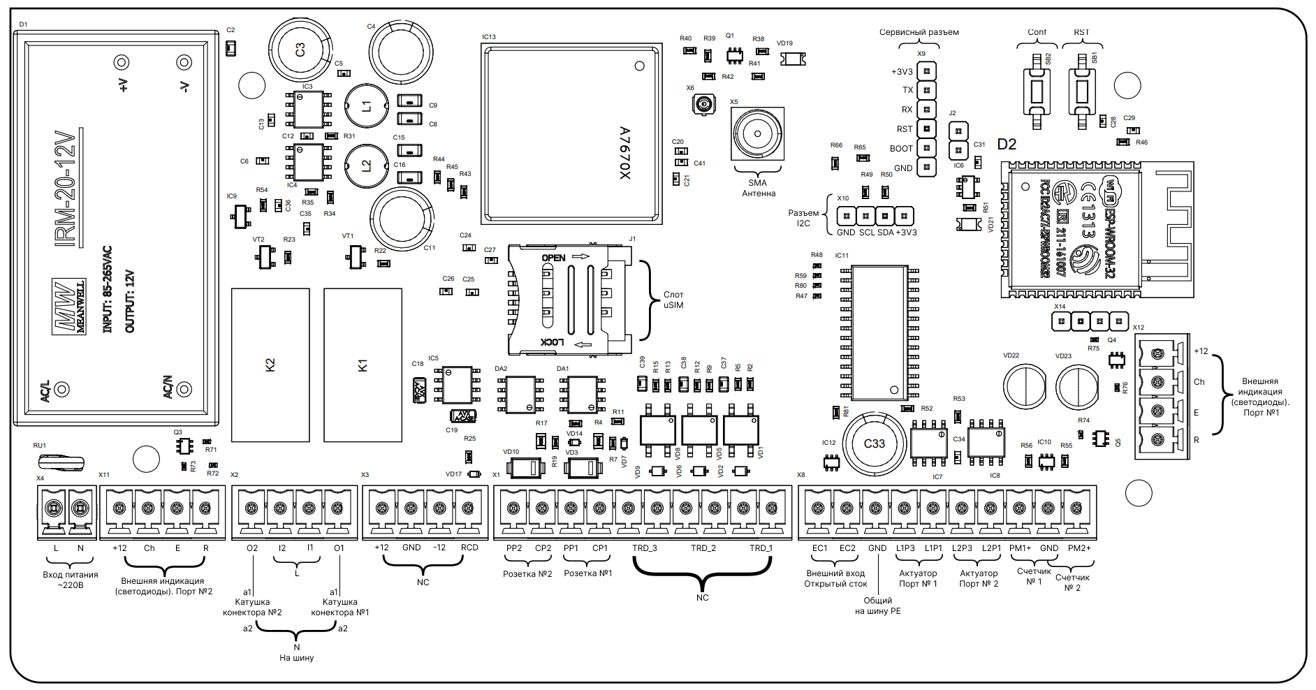
Description of control commands
1. Firmware update command (OTA)
- TS-GB_xxxxxxxxxxxx - insert station id
- retries==1 - to allow update
- retrieve_date - update start time
{
"GlobalID": "TS-GB_xxxxxxxxxxxx",
"location": "https://static.touch-station.com/ota/v5/gb/TS-GB_update.json",
"retrieve_date": "2022-07-27T15:12:12+00:00",
"retries": 1,
"retry_interval": 0
}
2. Command to update the firmware via DataTransfer (OTA)
- TS-GB_xxxxxxxxxxxx - insert station id
{
"GlobalID": "TS-GB_xxxxxxxxxxxx",
"messageId": "Set_Ota_Update",
"data": "https://static.touch-station.com/ota/v5/gb/TS-GB_test.json"
}
3. Request current communication parameters
- TS-GB_xxxxxxxxxxxx - insert station id
{
"GlobalID": "TS-GB_xxxxxxxxxxxx",
"messageId": "Get_Communication"
}
4. Request current settings
- TS-GB_xxxxxxxxxxxx - insert station id
{
"GlobalID": "TS-GB_xxxxxxxxxxxx",
"messageId": "Get_Settings"
}
5. Factory reset
- TS-GB_xxxxxxxxxxxx - insert station id
{
"GlobalID": "TS-GB_xxxxxxxxxxxx",
"messageId": "Set_DefaultSettings",
"data": "YES"
}
6. OCPP setup
- TS-GB_xxxxxxxxxxxx - insert station id
- data -"YES","NO" (not supported)
{
"GlobalID": "TS-GB_xxxxxxxxxxxx",
"messageId": "Set_Ocpp_Enable",
"data": "YES"
}
- data - address (required to end with /)
{
"GlobalID": "TS-GB_xxxxxxxxxxxx",
"messageId": "Set_Ocpp_URL",
"data": "ws://ocpp.touch-station.com/ocpp/"
}
- data - ID (max 25 characters)
{
"GlobalID": "TS-GB_xxxxxxxxxxxx",
"messageId": "Set_Ocpp_ID",
"data": "TEST_xxxxxxxxxxxx"
}
- data - port (does not change 80)
{
"GlobalID": "TS-GB_xxxxxxxxxxxx",
"messageId": "Set_Ocpp_Port",
"data": "80"
}
6. Settings for connecting to a custom WiFi hotspot
- TS-GB_xxxxxxxxxxxx - insert station id
- data - SSID
{
"GlobalID": "TS-GB_xxxxxxxxxxxx",
"messageId": "Set_WiFiUser_SSID",
"data": "TOUCH_STATION"
}
- data - password
{
"GlobalID": "TS-GB_xxxxxxxxxxxx",
"messageId": "Set_WiFiUser_PASS",
"data": "xxxxxxxxxxxx"
}
7. Settings for connecting via modem
- TS-GB_xxxxxxxxxxxx - insert station id -data-apn
{
"GlobalID": "TS-GB_xxxxxxxxxxxx",
"messageId": "Set_Modem_APN",
"data": "internet"
}
8. Charging current control
- TS-GB_xxxxxxxxxxxx - insert station id
- messageId - charging channel number:
- Set_CurrentLimit_CH1 - Type1
- Set_CurrentLimit_CH2 - Type2
- data - current in Amperes per channel (6A - 80A)
{
"GlobalID": "TS-GB_xxxxxxxxxxxx",
"messageId": "Set_CurrentLimit_CH1",
"data": "32"
}
9. Setting the value of the consumed power (as on the meter)
- TS-GB_xxxxxxxxxxxx - insert station id
- messageId - charging channel number:
- Set_Energy_CH1 - Type1
- Set_Energy_CH2 - Type2
- data - power consumption value displayed on the meter (WattHours)
{
"GlobalID": "TS-GB_xxxxxxxxxxxx",
"messageId": "Set_Energy_CH1",
"data": "1"
}
10. Install imp/kwh
- TS-GB_xxxxxxxxxxxx - insert station id
- messageId - charging channel number:
- Set_ImpOnkWh_CH1 - Type1
- Set_ImpOnkWh_CH1 - Type2
- data - number of pulses per kWт
{
"GlobalID": "TS-GB_xxxxxxxxxxxx",
"messageId": "Set_ImpOnkWh_CH1",
"data": "1000"
}
11. Run EVSE channel calibration
- TS-GB_xxxxxxxxxxxx - insert station id
- data -"YES"
{
"GlobalID": "TS-GB_xxxxxxxxxxxx",
"messageId": "Set_EvseCalibration",
"data": "YES"
}
12. Setting the actuator type
- TS-GB_xxxxxxxxxxxx - insert station id -data -"BISTABLE","MONOSTABLE"
{
"GlobalID": "TS-GB_xxxxxxxxxxxx",
"messageId": "Set_ActuatorType",
"data": "BISTABLE"
}
13. Block connector
- TS-GB_xxxxxxxxxxxx - insert station id
- messageId - charging channel number:
- Set_ConnectorLock_CH1 - Type1
- Set_ConnectorLock_CH2 - Type2
{
"GlobalID": "TS-GB_xxxxxxxxxxxx",
"messageId": "Set_ConnectorLock_CH1"
}
14. Unlock connector
- TS-GB_xxxxxxxxxxxx - insert station id
- messageId - charging channel number:
- Set_ConnectorUnlock_CH1 - Type1
- Set_ConnectorUnlock_CH2 - Type2
{
"GlobalID": "TS-GB_xxxxxxxxxxxx",
"messageId": "Set_ConnectorUnlock_CH1"
}